Beranda
/ Diy Wireless Charger Circuit - Qi DIY Wireless Charger Module Transmitter PCBA Circuit ... : Oscillator circuit consists of two n channel mosfets irf 540, 4148 diodes.
Diy Wireless Charger Circuit - Qi DIY Wireless Charger Module Transmitter PCBA Circuit ... : Oscillator circuit consists of two n channel mosfets irf 540, 4148 diodes.
Insurance Gas/Electricity Loans Mortgage Attorney Lawyer Donate Conference Call Degree Credit Treatment Software Classes Recovery Trading Rehab Hosting Transfer Cord Blood Claim compensation mesothelioma mesothelioma attorney Houston car accident lawyer moreno valley can you sue a doctor for wrong diagnosis doctorate in security top online doctoral programs in business educational leadership doctoral programs online car accident doctor atlanta car accident doctor atlanta accident attorney rancho Cucamonga truck accident attorney san Antonio ONLINE BUSINESS DEGREE PROGRAMS ACCREDITED online accredited psychology degree masters degree in human resources online public administration masters degree online bitcoin merchant account bitcoin merchant services compare car insurance auto insurance troy mi seo explanation digital marketing degree floridaseo company fitness showrooms stamfordct how to work more efficiently seowordpress tips meaning of seo what is an seo what does an seo do what seo stands for best seotips google seo advice seo steps, The secure cloud-based platform for smart service delivery. Safelink is used by legal, professional and financial services to protect sensitive information, accelerate business processes and increase productivity. Use Safelink to collaborate securely with clients, colleagues and external parties. Safelink has a menu of workspace types with advanced features for dispute resolution, running deals and customised client portal creation. All data is encrypted (at rest and in transit and you retain your own encryption keys. Our titan security framework ensures your data is secure and you even have the option to choose your own data location from Channel Islands, London (UK), Dublin (EU), Australia.
Diy Wireless Charger Circuit - Qi DIY Wireless Charger Module Transmitter PCBA Circuit ... : Oscillator circuit consists of two n channel mosfets irf 540, 4148 diodes.. As phones get smarter and come packed with a heavier processor, it gives us a great performance, but the only down side to this is the battery life. The transmitter section of wireless charger circuit consists of a dc power source, oscillator and a transmitter coil. Wireless cellphone charger circuit | homemade circuit projects a wireless cellphone charger is a device that charges a compatible cellphone or mobile phone placed close to it, through high frequency wireless current transfer, without any physical contact. You'll have to plug the wireless receiver into your phone's charging port, then hide it on the back of the device with a case. Inductive chargings (also known as wireless charging or cordless charging) is a type of wireless power transfer.
Oscillator circuit consists of two n channel mosfets irf 540, 4148 diodes. As phones get smarter and come packed with a heavier processor, it gives us a great performance, but the only down side to this is the battery life. This is a li po charger and balancer project for rc hobbythe charger circuit is based on the circuit of electron head and all folks in the diy electronics topic on. It uses electromagnetic induction to provide electricity to portable devices. You can also use this project as a wireless charger for several devices by doing some changes in this circuit.
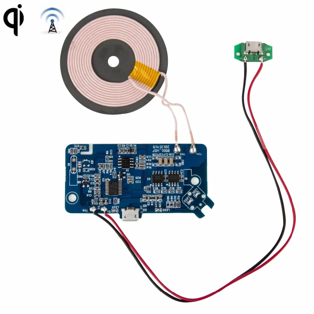
Qi Wireless Charger PCBA Circuit Board With 3 Coil ... from i.ebayimg.com When the mobile phone is placed above the wireless charger, the induced magnetic field produces electric current in the receiver coils which is then transferred to and controlled by the charging circuit in the phone. The most common application is the qi wireless charging st… Wireless cellphone charger circuit | homemade circuit projects a wireless cellphone charger is a device that charges a compatible cellphone or mobile phone placed close to it, through high frequency wireless current transfer, without any physical contact. A constant dc voltage is provided by a dc power source, and this dc signal is the input to the oscillator circuit. You'll have to plug the wireless receiver into your phone's charging port, then hide it on the back of the device with a case. Ebay is your friend for tech like this! 3inches, compatible with iphone11/11pro, iphone x/xs/xr/8/8 plus 35 $25 99 A wireless charging system needs to contain the following circuit elements:
This charging circuit in the phone provides controlled optimal power to charge the battery properly.
When the mobile phone is placed above the wireless charger, the induced magnetic field produces electric current in the receiver coils which is then transferred to and controlled by the charging circuit in the phone. A constant dc voltage is provided by a dc power source, and this dc signal is the input to the oscillator circuit. David, i searched on google for wireless diy qi charger pcba circuit board w/coil charging and found quite a few products. The phenomena of wireless power transmission include the inductive energy that transmits from a transmitter coil to a receiver coil through an oscillating magnetic field. Project file on free circuit editor: Wireless cellphone charger circuit | homemade circuit projects a wireless cellphone charger is a device that charges a compatible cellphone or mobile phone placed close to it, through high frequency wireless current transfer, without any physical contact. Diy embedded hidden wireless charger, heheda 10w 7.5w 5w usb3.0 fast qi wireless charging station with 3m film for desk hole with dia. This is a li po charger and balancer project for rc hobbythe charger circuit is based on the circuit of electron head and all folks in the diy electronics topic on. The wireless charger has allegedly worked at a distance of 10 ft. This circuit was intentionally designed to be simple. The first circuit is transmitter circuit used to produce voltage wirelessly. Diy wireless mobile phone charger 4 steps. Borrowing from the concept of the wireless chargers on the market.
The transmitter section of wireless charger circuit consists of a dc power source, oscillator and a transmitter coil. This is a li po charger and balancer project for rc hobbythe charger circuit is based on the circuit of electron head and all folks in the diy electronics topic on. The transmitter circuit consists of dc source, oscillator circuit and a transmitter coil. It is not trivial and requires strict timing. Project file on free circuit editor:
Aliexpress.com : Buy Qi PCBA DIY Wireless Charger Sample ... from ae01.alicdn.com Project file on free circuit editor: Diy wireless mobile phone charger 4 steps. Among various arduino projects on the blog spot site, a diy task has been published by ams gold that explains as to how anyone can make a wireless charger at home and that too at the minimum possible cost. This is how your device will receive the charge. The most common application is the qi wireless charging st… It uses electromagnetic induction to provide electricity to portable devices. Reply 6 years ago on introduction. Hi davidm14, we just updated the first step.
When switched on, the circuit may be expected to generate a strong magnetic flux around the coiled tracked, equivalent to the input power.
Pcba circuit board accompanied by 3 coil wireless. The phenomena of wireless power transmission include the inductive energy that transmits from a transmitter coil to a receiver coil through an oscillating magnetic field. The transmitter circuit consists of dc source, oscillator circuit and a transmitter coil. This circuit was intentionally designed to be simple. You'll have to plug the wireless receiver into your phone's charging port, then hide it on the back of the device with a case. Wireless cellphone charger circuit | homemade circuit projects a wireless cellphone charger is a device that charges a compatible cellphone or mobile phone placed close to it, through high frequency wireless current transfer, without any physical contact. Gikfun qi wireless charger pcba circuit. When switched on, the circuit may be expected to generate a strong magnetic flux around the coiled tracked, equivalent to the input power. Diy wireless mobile phone charger 4 steps. It is not trivial and requires strict timing. While in intensive use the phones may provide only a few hours of battery life, fortunately there is… 5w qi fast charging wireless charger pcba diy standard accessories transmitter module coil circuit board $5.99 qi fast wireless charger pcba circuit board single coil wireless charging modules diy for iphone x 1 offer from $23.49 According to the video, all you need is your charger, a copper wire, electrical tape and a magnet.
Ebay is your friend for tech like this! A set of coils that serve as a primary transmitter and secondary for the receiver. Gikfun qi wireless charger pcba circuit. $2/5pcs 2layer & $2/5pcs 4layer pcbs: It uses electromagnetic induction to provide electricity to portable devices.
DIY Qi Standard Wireless Charging Coil Receiver Module PCB ... from ae01.alicdn.com Inductive chargings (also known as wireless charging or cordless charging) is a type of wireless power transfer. Gikfun qi wireless charger pcba circuit. The first circuit is transmitter circuit used to produce voltage wirelessly. Hi davidm14, we just updated the first step. Wireless charging is simply two small coils of w. Diy wireless mobile phone charger 4 steps. You'll have to plug the wireless receiver into your phone's charging port, then hide it on the back of the device with a case. A set of coils that serve as a primary transmitter and secondary for the receiver.
Project file on free circuit editor:
Wireless cellphone charger circuit | homemade circuit projects a wireless cellphone charger is a device that charges a compatible cellphone or mobile phone placed close to it, through high frequency wireless current transfer, without any physical contact. Ebay is your friend for tech like this! Make sure the lc values are exactly similar to the tx lc values. Check out a small demo board i put together to demonstrate qi wireless. The coil for the receiver circuit for this high current wireless battery charger is exactly similar to the transmitter coil. A set of coils that serve as a primary transmitter and secondary for the receiver. This charging circuit in the phone provides controlled optimal power to charge the battery properly. You 100% could make your own coil and driving circuit but it would be an endeavor for the sake of bragging to do it. This circuit was intentionally designed to be simple. You'll have to plug the wireless receiver into your phone's charging port, then hide it on the back of the device with a case. It is not trivial and requires strict timing. David, i searched on google for wireless diy qi charger pcba circuit board w/coil charging and found quite a few products. Any type of oscillator capable of producing the resonant frequency.